Mark Lamb’s Balanced Bride of Zen Pre-amp and Zen Power Amps
I have built two Nelson Pass designs, Balanced Bride of Zen preamp and two Zen Power Amps, and am very pleased with the end results. I have to thank Nelson for providing the designs to the public and providing insights via private email. These are the only pieces of electronic equipment that I have ever built, and the fact that both worked perfectly when first hooked up is a testament to Nelson’s great and simple designs and his well written articles.
I built my Balanced Bride of Zen preamp in 4Q98-1Q99 and built my two Zen Power Amps in 3Q00.
Some of the general concepts that I used on both designs are:
- Outboard power supplies to isolate AC from the signal circuitry.
- Point-to-point wiring, NO PCBs, using component leads when ever possible.
- Teflon insulated, solid core, pure silver wiring within the signal path.
- By-pass electrolytic capacitors with 1.5 uF polypropylene capacitors to lower ESR.
- By-pass signal path polypropylene capacitors with 0.1 uF Multicap tin foil & film capacitors.
- Single star signal ground point for each chassis.
- Signal ground is separate from chassis ground by using a thermistor.
- Well dampened chassis using a Soundcoat-like dampening material.
Balanced Zen Pre-Amp
The deviations that I made from Nelson’s line stage design are:
- Input power cord is a “Homebrew” based on TNT’s Twisted Snakes using hospital grade Marinco plugs and Schurter 15amp IEC plug.
- Chassis IEC connector is a Corcom 3EEB1 with EMI filter.
- AC capacitor C107 is eliminated due to the filtered IEC connector.
- Power supply capacity is doubled, with a single Plitron 120VA, 60+60V transformer instead of two Avel Lindberg 30VA, 30+30V transformers.
- Two copies of all circuitry downstream of the diode bridges, B101 & B102.
- Capacitors C101 and C102 are by-passed with GE 41L2151 5%, 250V, 1.5 uF metalized polypropylene capacitors.
- Power supply is outboard in 10″x6″x3.5″ LMB aluminum box attached to the preamp via an umbilical composed of five braided 16-gauge stranded copper conductors with a Neutrik 5-pin XLR connector (2 +60V, 2 -60V, & signal ground) and a separate 20 gauge solid copper conductor for the chassis ground.
The deviations that I made from Nelson’s line stage design are:
- Input resistors R18 and R19 are eliminated.
- Input pots P1 and P2 are replaced with a single discrete stepped-attenuator per channel (w/ 1dB per step, balanced dual-mono, ladders using 0.5% Holco H8 resistors and Electroswitch 12-position, 1-pole, 4-deck non-shorting switchs) to perform fine volume control (-0dB to -11dB). With separate attenuators for each channel, L-R balance can be adjusted.
- Output pots P3 and P4 are replaced with a single stepped-attenuator for both channels (w/ 5dB per step, balanced shunt attenuator using metal film resistors and an Electroswitch 12-position, 1-pole, 4-deck shorting switch) to perform coarse volume control (-0dB to -55dB). These switches are placed between the junctions of R9/R11 and R10/R12 and signal ground. The attenuation is calculated by calculating the voltage divided between R9 or R10 and the paralleled switch and R11 or R12 (the lower the switched resistor, the higher the voltage drop through R9 or R10, and thus the lower the volume).
- Gain Pot P5 is replaced with a single discrete stepped variable gain switch for both channels (w/ 4dB per step, using metal film resistors and an Electroswitch 6-position, 2-pole, 1-deck non-shorting switch) to perform coarse gain control.
- Resistor R15 is eliminated, but accounted for in the gain switch, above.
- Preamp’s outputs are at the junctions of R9/R11 and R10/R12.
- Signal path resistors R7, R8, R9, and R10 are Caddock MK-132 type.
- Resistors R11, R12, R13, and R14 are 0.5% Holco H4 type.
- Capacitors C3 and C4 are by-passed with GE 41L2151 5%, 250V, 1.5 uF metalized polypropylene capacitors.
- Signal path capacitors C1 and C2 are by-passed with 400V, 0.1 uF Multicap PPFX-S tin foil & film capacitors.
- Signal path capacitors C1 and C2 are GE 41L6100 5%, 600V, 10 uF metalized polypropylene capacitors.
- The input selector switch is a Greyhill 6-position, 2-pole, 2-deck non-shorting switch.
- The chassis is a 17″x10″x4″ aluminum box with a 0.25″ brushed aluminum face plate. This was purchased from Spire Audio (no longer in business, I think). Spire punched all of the rear holes for I/O (although some filing was necessary to fit the XLRs) and the front holes for the switches and countersunk the front holes for the knobs. Spire did all this for about $110.
- All signal path wiring was solid core fine silver wire with teflon dielectric.
- “Key” interconnects into and out of preamp are hardwired in the preamp (no RCA jack) and are homemade braiding 12 pieces of 30ga fine silver & teflon dielectric using WBT-144 locking RCAs.
- XLR input and output jacks are gold-plated Neutrik.
- RCA input and output jacks are gold-plated with teflon dielectric.
- H4 type.
- Capacitors C3 and C4 are by-passed with GE 41L2151 5%, 250V, 1.5 uF metalized polypropylene capacitors.
- Signal path capacitors C1 and C2 are by-passed with 400V, 0.1 uF Multicap PPFX-S tin foil & film capacitors.
- Signal path capacitors C1 and C2 are GE 41L6100 5%, 600V, 10 uF metalized polypropylene capacitors.
- The input selector switch is a Greyhill 6-position, 2-pole, 2-deck non-shorting switch.
- The chassis is a 17″x10″x4″ aluminum box with a 0.25″ brushed aluminum face plate. This was purchased from Spire Audio (no longer in business, I think). Spire punched all of the rear holes for I/O (although some filing was necessary to fit the XLRs) and the front holes for the switches and countersunk the front holes for the knobs. Spire did all this for about $110.
- All signal path wiring was solid core fine silver wire with teflon dielectric.
- “Key” interconnects into and out of preamp are hardwired in the preamp (no RCA jack) and are homemade braiding 12 pieces of 30ga fine silver & teflon dielectric using WBT-144 locking RCAs.
- XLR input and output jacks are gold-plated Neutrik.
- RCA input and output jacks are gold-plated with teflon dielectric
Balanced Zen Pre-Amp Photo descriptions:
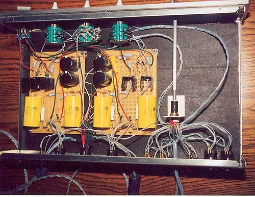
Direct overhead of the line stage, with the top of the photo being the front. The center aqua switch on the photo’s top (attached to the preamp’s faceplate) is the balanced shunt attenuator, and the aqua switches flanking it are the right and left fine ladder attenuators. The black switch at the photo’s top left is the gain switch. The red switch in the lower right attached to the shaft extension is the input selector. Notice that one of the RCA inputs is directly soldered to the switch and is composed of twelve separately teflon insulated 30gauge fine silver conductors. Like wise, one of the RCA outputs is directly soldered to the signal boards and is composed of twelve separately teflon insulated 30gauge fine silver conductors. The star signal ground point is at the 5-pin XLR input. An 18gauge solid core white copper wire which attaches to the shunt attenuator is solder directly to the signal ground input pin from the power supply; this wire has been stripped about 1″ and all other grounds are wrapped and soldered to this end which is attached to the XLR. The black on the chassis bottom, sides, and top (not shown) is a Soundcoat-like dampening material.
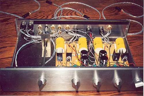
Frontal overhead view of the line stage, with the top of the photo being the back. The knobs are from left to right: input selector, left channel fine attenuator, master coarse shunt attenuator, right channel fine attenuator, and gain switch.
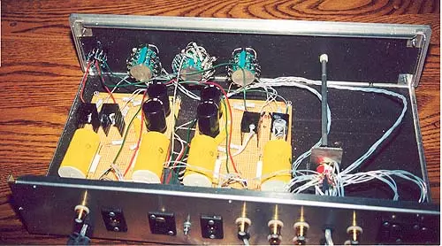
Rear overhead of the line stage, with the top of the photo being the front.
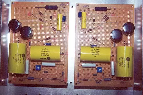
Close-up view of right channel signal board.
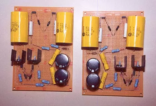
Close-up view of left and right channel signal board. Note the symmetry.
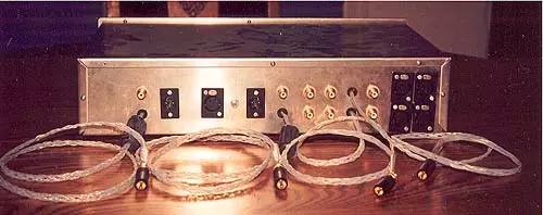
Rear view of line stage chassis, showing inputs and outputs. From left to right: right channel RCA outputs (direct connect on bottom), right channel XLR output, 5-pin XLR power input, screw & nut for chassis ground connection, left channel XLR output, left channel RCA outputs (direct connect on bottom), four RCA inputs including 1 direct connect (left on top; right on bottom), and two XLR inputs (left on top; right on bottom).
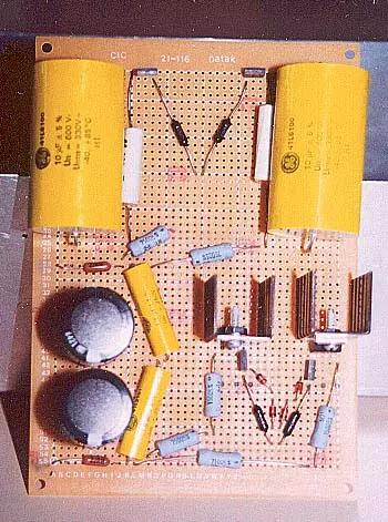
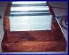
View of power supply board propped up against power supply chassis. The voltage rails are left to right: +60V, +60V, -60V, and -60V. The signal ground is a star ground point on the underside of the board in the center made from the downstream lead of the thermistor.
I really like my balanced Zen preamp. It is better than the passive shunt attenuator I built prior, which was better than the Parasound PFET/900 II in use prior to the passive. Before I built it, I had decided to build Zen poweramps and wondered if the single-ended Zen preamp would be a better match. So I emailed Nelson Pass, and he recommended the balanced preamp.
If you build the balanced Zen preamp and plan to use it with a Zen poweramp, make sure to have a switch to vary the preamp’s gain (I used a 6-position, 2-pole switch with discreet metal film resistors), as a Zen poweramp will need about 20 dB more gain than a typical poweramp.
Zen Power Amp
The deviations that I made from Nelson’s The Return of Zen power supply stage are:
- Input power cord is a “Homebrew” based on TNT’s Twisted Snakes using hospital grade Marinco plugs and Hubbell 20 amp IEC plug.
- Chassis IEC connector is a Hubbell 20amp IEC chassis connector.
- Power supply transformer is a Plitron 300VA, 25+25V transformer instead of an Avel Lindberg 300VA, 30+30V transformers.
- Signal ground is separate from chassis ground by using a thermistor.
- Capacitor C1 is by-passed with GE 41L2151 5%, 250V, 1.5 uF metalized polypropylene capacitor.
- Power supply is outboard in 12″x7″x4″ LMB aluminum box attached to the amp via an umbilical composed of four 12-gauge solid copper conductors with a Neutrik 3-connection Powercon connector (+32V, +32V, & signal ground) and a conductor for the chassis ground.
- One of power supplies has a switched AC receptacle (to which a power strip containing the 12V wall-wart power supplies for the whisper fans is plugged into).
The deviations that I made from Nelson’s The Return of Zen amplifier stage are:
- There is only one RCA input per amplifier, with both of the complete amplifier stages being connected in parallel. The end result is bi-amped monoblocks, with increased power per channel and more friendly impedance match with the bi-wired speakers.
- Output MOSFETs are IRFP044N-ND, which are supposedly a update of the IRFP040 mentioned as the lowest distortion option (compared with the IRFP140 and IRFP240) in Nelson’s articles, but since discontinued.
- Signal path resistors R8, R10, and R11 are Caddock MK-132 type.
- Capacitor C5 is by-passed with GE 41L2151 5%, 250V, 1.5 uF metalized polypropylene capacitor.
- Signal path capacitors C9 and C19 are by-passed with 400V, 0.1 uF Multicap PPFX-S tin foil & film capacitors.
- Signal path capacitor C9 is GE 41L6100 5%, 600V, 10 uF metalized polypropylene capacitor.
- Signal path capacitor C19 is GE 41L7471 5%, 600V, 4.7 uF metalized polypropylene capacitor.
- The each chassis is a 12″x10″x3″ LMB aluminum box which is wrapped in a Soundcoat-like dampening material and 4″x1″ solid black walnut. Four, 12″ AAVID #67075 heatsinks form the top of the chassis. A 0.5″ teak frame containing two 3.125″ whisper fans is attached on the back.
- All signal path wiring was solid core fine silver wire with teflon dielectric.
- RCA input jacks are Cardas GRFA silver/rhodium-plated with teflon dielectric.
- Speaker output terminals are WBT-0744 midline terminals.
- Power supply input is a Neutrik 3-connection Powercon connector (+32V, +32V, & signal ground) and a separate post for the chassis ground.
Zen Power Amp Photo descriptions:
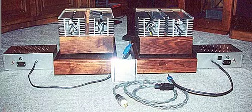
Front view of the completed pair of Zen Amplifiers. The amps (12.75″x14.5″x8.5″) are sitting on their amp stands and flanked by their power supplies. In the foreground is one of the homemade powercords.
The amp stands (14″x20″x3.5″) are composed of two pieces of 12″x18″x0.75″ MDF sandwiching a piece of fiberboard attached by glue and screws. The MDF has Soundcoat-like dampening material on the top and is skirted by 3.5″x1″ solid black walnut with mitered corners. The four corners of the bottom piece of MDF are MDF footers with steel spikes.
Side view of the Zen Amplifier sitting on its amp stand.
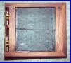
Bottom view of the Zen Amplifier. The black is the Soundcoat-like dampening material attached to the bottom of the 12″x10″x3″ LMB aluminum box with ventilation holes. At the front and back of the bottom are 1″ thick solid black walnut rails which support the aluminum box.
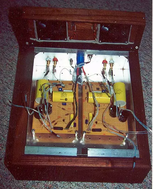
Top frontal view of the Zen Amplifier with heatsinks containing Q1 and Q2 removed. Note the aluminum right angles added to the front and rear to serve as a shelf for the heatsinks. The wiring to the negative speaker terminals is composed of 8 individually teflon insulated 24 gauge solid silver conductors. All of the wiring connecting the MOSFETs to the boards are composed of 2 individually teflon insulated 24 gauge solid silver conductors.
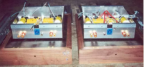
Rear view of the 12″x10″x3″ LMB aluminum box before it was put in the walnut frame. These boxes are are sitting on their unfinished amp stands. All outside surfaces (except the lower back panel with the I/O) of the aluminum box had the Soundcoat-like dampening material attached. In the center of the back panel is the blue Neutrik 3-connection Powercon connector flanked by a single Cardas GRFA RCA input jack (upper) and a post for the chassis ground (lower). On both sides of the back panel are the WBT-0744 speaker output terminals.
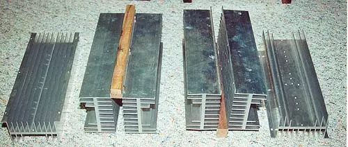
AAVID #67075 12″ heatsinks. The center two heatsinks are screwed to a black walnut rail, which fits into the notch between the aluminum right angles.
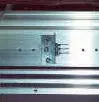
View of how the MOSFETs are attached to the heatsinks. Small sections of aluminum right angles are cut and three holes drilled to sandwich the MOSFET to the heatsink. This should allow for more pressure on the MOSFET resulting in more efficient heat transfer. It also adds an additional fin in the wind tunnel created by the whisper fans. The screws are 6-32’s, which are much easier to tap than 4-40’s.
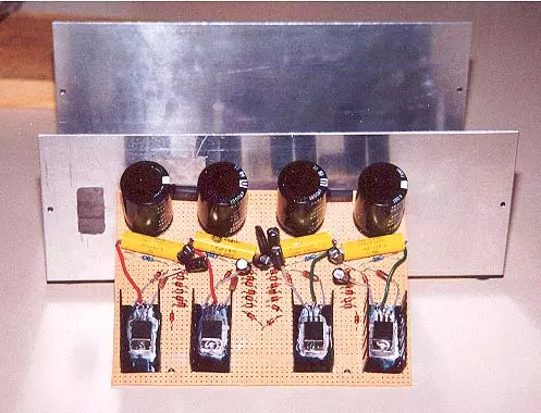
Top view of the power supply with its top removed. The black is the Soundcoat-like dampening material attached to the inside of the 12″x7″x4″ LMB aluminum box. There are two +32V voltage rails. The signal ground is a star ground point on the underside of the board in the center made from the downstream lead of the thermistor. Notice that two extra holes were drilled into the board for extra standoffs to support the weight of the inductors.
View of the two signal boards. Note symmetry.
My main challenge with the Zen poweramps was getting enough heatsinking. I first bought 4 of the largest heatsinks I could find a couple of years ago from American Science and Surplus. These finned sinks were 10.75″x4.75″x1.5″. I hoped to use 2 per amp as the sides or top of the amp. Using alligator clips to attached the power supply, signal board, and Q1/Q2 on the sinks, I gave it a try. Much to my displeasure, it was way too hot, about 95 degrees C. I then had to find larger sinks. I thought I found some at MECI. I ordered 8 inverter sinks from MECI, but they had sold out. I then did an internet search for heatsinks (found Altavista’s search engine was the best for this). I found what I need at MPJA, sinks that seemed to be AAVID #67075’s for $7 for 12″ sections. These sinks are 12″x4.75″x2.625″ with fins on two sides. I ordered 8, hoping to have to use only 4. I was lucky in that MPJA had only 9.
AAVID #67075’s have a thermal resistance of 1.5 degrees C/W/3″, but I had to make several adjustments to get the effective thermal resistance for my application. Without these adjustments, it would seem likely that 2 sinks per amp would be adequate (1.5 / 4 = 0.375). But the stated thermal resistance assumes 75 degree C temperature rise above ambient, about 30-40 degrees too high. Also, unless the application has transistors evenly with each one centered in a 3″ section, there would have to be a length adjustment. All in all the calculated thermal resistance for my 12″ sections assuming a single transistor per was 0.95 degrees C/W (1.5 * 0.54 * 1.17), not 0.375.
I ended up having to use 4 sinks per amp, one each for every Q1 or Q2 and still had to add two 3.125″ whisper fans to each amp. I purchased the 12V fans from MPJA for $5 each, plus $1.50 for wall wart power supplies.
My experience with these amps is that they have high “natural” resolution, NOT artificially hopped high frequencies. They are also smooth and relaxing to listen to. They sound considerably better than the Parasound HCA-1200mkII, which is a good sounding amp in its own right.
I have been using these amps heavily for 10 months in a bi-amping, monoblock arrangement, and I have not noticed any power deficiencies.
Complete Stereo System
- “Homebrew” Focal Daline MTM transmission line tower speakers. These are similiar to JMLabs’ Daline 6.1 using two Focal 6V415 midbass’s and one Focal TC-90tdx tweeter, except: double box construction; with rabbeted joints; dadoed transmission line; interior damped with Black Hole 5 and Black Hole Pad; front baffle w/ 0.75″ radius edge; outboard crossover; and tweeters offset 1″ towards the inside edge (mirror imaged). These speakers weigh 110 pounds, each.
- “Homebrew” Nelson Pass designed Balanced Bride of Zen preamp, with: a doubled, dual-mono, outboard power supply; discrete stepped-attenuators (w/ 1dB per step, balanced dual-mono, ladders using 0.5% Holcos on the input, & 5dB per step balanced shunt attenuators at the output); discrete stepped variable gain (with 6, 4dB per step levels); by-passed polypro signal capacitors w/ 0.1uF Multicap tin foil & film caps; 4-nines pure silver & teflon signal wire; Caddock resistors in signal path, and heavily damped chassis.
- “Key” interconnects into and out of preamp are hardwired in the preamp (no RCA jack) and are homemade braiding 12 pieces of 30ga 4-nines pure silver & teflon dielectric using WBT-144 locking RCAs.
- Power amp is two stereo “Homebrew” Nelson Pass designed Zen Amplifiers (10W/ch, single ended, single stage, pure Class-A) in a bi-amping, monoblock arrangement. The Zens have outboard power supplies; Caddock resistors in the signal path; by-passed polypro signal capacitors w/ 0.1uF Multicap tin foil & film caps; 4-nines pure silver & teflon signal wire; 20 amp Hubble IEC connectors; Cardas rhodium input RCA jack; WBT midline output binding posts; and heavily damped chassis. I used IR044 output MOSFETs, which are supposedly a update of the IR040 mentioned as the lowest distortion option (compared with the IR140 and IR240) in Pass’s articles, but since discontinued.
- Sony SCD-777es SACD/CD player.
- Speaker wire is double runs of “Homebrew” silver cable. This cable is made from 12 conductors of 22-gauge, dead soft annealed fine silver, individually coated with Caig ProGold and hand stuffed into 20-gauge PTFE teflon tubing. I previously used double runs of Kimber 4TC.
- Power Conditioner: Monster HTS-5000.
- Power Cables: “Homebrew” based on TNT’s Twisted Snakes using hospital grade Marinco plugs and Schurter 15amp IEC’s or Hubble 20amp IEC’s (for poweramps).
Mark Lamb