Drawings by Kirk Rader.
The importance of phase response in the audio chain has been brought to greater focus recently by equipment claims of phase coherency, (the output signal has the same phase relationships as the input signal). It is not particularly obvious that two different frequency components of a signal can go into a device at precisely the same time and emerge at different times, but it is extremely common. All audio components distort the phase of the signal to some degree-even air alters the time alignment of a signal, but the biggest offenders are loudspeakers and their crossover networks. Phase shifts in the audio signal destroy the wave shape of the important attack characteristics of many instruments and hamper our ability to perceive the localization of the image,smearing the apparent source. They can change the steady state waveforms of vocal sounds so that the singer seems to be ten feet wide.
Historically, the phase integrity of the audio signal has been considered much less important than amplitude and harmonic/intermodulation distortions, but as more of those problems are solved and the quality of reproduction improves, phase distortion stands out in greater relief. The question of the audibility of these distortions has become the object of heated discussions regarding the perceivability of absolute phase, frequency dependent phase shifts, and the rate of phase shift. Nonetheless we know that the ear is sensitive to phase and uses phase cues to help determine directionality. In the belief that proper attention to phase does produce better sound, I will discuss the design of crossover networks which ever minimum phase distortion.
WHY USE CROSSOVERS?
A necessary evil, the crossover network exists solely to ameliorate the inability of most loudspeaker drivers to cover the full audio range. Treated as a mass controlled piston working into an acoustic load, the typical cone loudspeaker derives the flatness of its response from the cancellation of two opposing effects-its excursion (which decreases as the square of the frequency), multiplied by the resistance of the acoustic load (which increases as the square of the frequency).
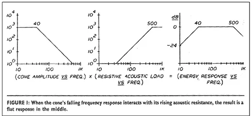
Figure 1 shows this relationship on normalized logarithmic scales. The two functions cancel each other to create a flat acoustic output between the roll off points. At some high frequency (where the acoustic wavelength is less than the circumference of the cone) the acoustic resistance levels off to a constant value. Since the cone’s excursion decreases by the square of the frequency, the resulting frequency response curve (excursion times acoustic resistance) rolls off at 12dB/octave. At the low frequency resonance of the driver, where to excursion is dominated by the compliance of the suspension instead of the mass of the cone, another rolloff appears, also at 12dB/octave. Generally cone drivers don’t work well over more than about a 10 to 1 frequency range, and to cover the audio spectrum from 20Hz to 20kHz you might need three different drivers, each designed for a specific range-20 to 200Hz for the woofer, 200 to 2000Hz for a midrange,and 2 to 20kHz for the tweeter. You could send a full range signal to all the drivers in parallel, but would discover quickly that they fail to reproduce outside their range. As they struggle to do so, severe distortion and possible damage may occur. The crossover network divides the sound among the drivers. Ideally when the drivers reproduce the signals sent to them, their outputs blend together to form an acoustic copy of the original signal as if the division had never taken place.
SQUARE WAVES SHOW PHASE CHANGES
One of the reasons the square wave is a useful test signal is that its shape is extremely sensitive to any variation in either amplitude or phase. It consists of a rich array of harmonics, and any alteration of their amplitude and phase deforms that squareness. I suppose the perfect high fidelity system would have to pass a square wave test, where a square wave would be encoded onto the appropriate medium and the resulting playback would create an acoustic square wave in the vicinity of the listener’s ear. Most parts of the audio chain pass square waves quite well when designed carefully. Loudspeakers have the greatest problem, and although some present good square waves at particular frequencies and angles, to date I have not seen a loudspeaker which passes a general square wave test.
When we send a square wave into a loudspeaker system and observe the resulting image on an oscilloscope screen, we see little resemblance to a
square wave except the original periodicity . The loudspeaker drivers, the room, and the microphone have all degraded the waveform. If we could eliminate all of these sources of distortion, we still might find our square wave grossly modified, the phase seriously distorted by the crossover network.
CROSSOVERS ALTER PHASE
All filters, active or passive, alter the phase. However, with some types of filters, when the low pass and high pass outputs are mixed back together, the original phase and amplitude relations are re-created precisely. Such crossover filters are phase coherent and their high and low pass outputs are phase complementary. To evaluate the coherence of a given pair of filters, we measure the electrical sum of their outputs, then mathematically add them; examining the result for amplitude and phase distortion. On some filters we find that inverting the output of the high or low pass filter results in more accurate total amplitude or phase response, and we will examine those possibilities also.
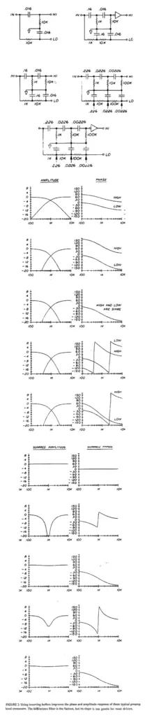
Figure 2 shows the results of such a test with some reasonably common crossover network types. These particular circuits are designed for biamplified systems, with low source impedance and high load impedance. Note the use of phase inverting buffers to invert the in some cases. (Of course this could be achieved more easily in a real system by inverting the polarity of the loudspeaker terminals.)
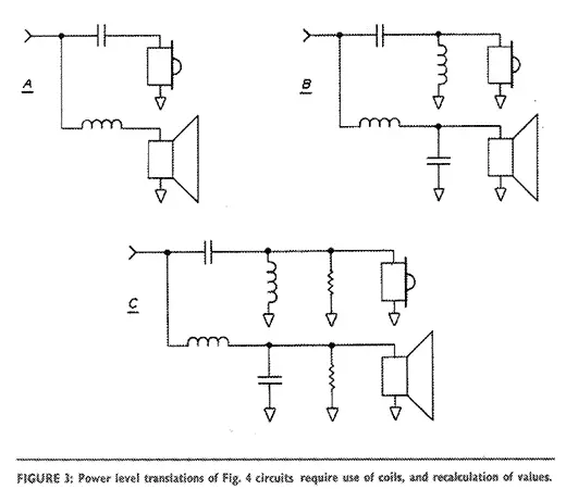
The topologies in Fig. 3 are for power, rather than preamp levels, using coils. As the textbooks are fond of saying, calculation of the values is left as an exercise to the reader. The 6dB/octave and the inverted 12 and 18dB/octave examples yield sums which are quite fiat, and remarkably, we see that the 12 and 18dB/octave cases both yield identical amplitude and phase results. Of all these filters only one, the lowly 6dB/octave crossover has both accurate amplitude and phase response when the outputs are reassembled.
SIMPLE BUT EFFECTIVE
In applications where the drivers have wide bandwidth and can tolerate the low rolloff rate, the6dB/octave crossover can give excellent results, particularly with planar drivers, such as electrostatic systems and Magnepans.
The circuit of Fig. 4 has given me excellent results with the Tympani 1D’s and MG 2A’s and serves as a good example of how well simple inexpensive approaches work. I have not had the opportunity to try it with their newer SMG’s, but I expect similar improvements over the stock systems. Using both capacitors and coils, it presents a flat input impedance of 10kohm or higher.
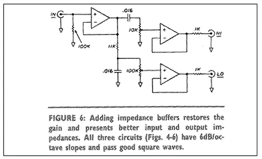
Those who wish to dispense with coils and whose preamp can drive a 5kohm load might try the equivalent circuit of Fig. 5, which gives the same results with a few decibels loss of gain. The circuit of Fig. 6 (which uses active impedance buffers to give the circuit a very high input impedance and a very low output impedance) does not have this loss. Various types of buffers are possible. IC buffers (such as the LM 302 or LM 310) op amps (whose output is connected to the inverting input), and simple one-device emitter/source/cathode voltage followers without negative feedback are suitable. The circuits of Figs. 4-6 all pass our square wave test and all have6dB/octave slopes.
SUMMING FOR FLAT RESPONSE
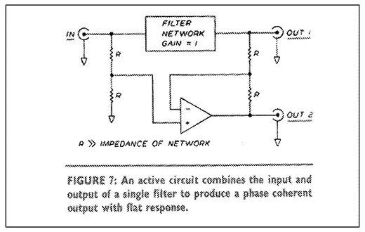
Even more interesting is the technique illustrated in Fig. 7. An active circuit assembles a phase complementary output from the difference between the input and the output of a single filter. This ensures that the sum of the two outputs will be perfectly flat in amplitude and phase. To be effective, the filter should exhibit unity gain in its passband, or the rolloff characteristic will have a shelf hike a conventional tone controll, but otherwise it can be any type of filter.
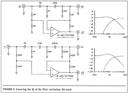
This approach allows the use of higher order filter slopes in a phase coherent crossover as shown in Fig. 8, where we note some interesting phenomena. The precise complement of a maximally flat 12or 18dB/octave filter has a peak which increases with the slope and Q of the filter, and it always exhibits a 6dB/octave slope. One of these minor drawbacks, the peak, can be reduced by lowering the Q of the filter as in the examples of Fig. 9 where the less than maximally flat characteristics are those of Fig. 2.
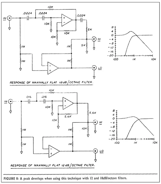
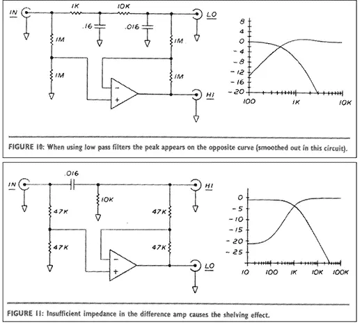
Figure 10 shows us that the effect is similar but reversed if you use a low pass filter in this configuration instead of a high pass. Unfortunately, I don’t know of a way the complementary output can be made to roll off at a slope greater than6dB/octave, and you must choose whether it will be the low pass or the high pass based on information about the drivers. Most of the time you should assign the higher slope to the tweeter, since it generally needs more protection from out of band signals. In such filters, the resistances in the differencing amplifier must be very much greater than the output impedance of the filter. Figure 11 shows what happens when they are only 5 times greater: the rolloff curve shelves at about -20dB.This is not a very desirable characteristic, but often it is not very practical to place multimegohm resistances in the differencing circuit because of the noise and the input bias currents of the op amp. Figure12 shows an easy solution to this potential problem. Buffering the output of the filter gives it a near-zero output impedance, and completely eliminates this effect.
TOTAL SYSTEM RESPONSE
So far we have considered only the phase and amplitude performance of the crossover network and how easily you can achieve phase coherency in such a device. However Mother Nature is not going to let us off so lightly. These networks drive loudspeaker elements and while we can make filters perfect, the acoustic sum includes the phase and amplitude distortions of the drivers. Robert Bullock’s interesting work on the sensitivity of conventional crossover networks to the imperfections of drivers inspired me to examine phase coherent filters for the same phenomena.
The computer model for two different tweeters and two different woofers shown in Fig.13 is consistent with our previous analysis of the mass controlled piston. One case allows for a one octave margin between the drivers’ rolloffs and the crossover point (500Hz for the tweeter, 2000Hz for the woofer, and 1000Hz crossover), and the second case allows for a two octave margin. The actual acoustical output is the sum of the crossover and driver characteristics. I tried various combinations in the computer model and found (Fig. 14) that severe amplitude and phase distortion occur in all cases.
Does this mean that phase coherent crossovers are useless? Not necessarily. Examples of these filters have been known to work well, particularly with planar drivers, which are not precisely modeled as pistons, and do not exhibit the severe amplitude anomalies we might expect. However, note that while the filter may be advertised honestly as phase coherent this does not guarantee the system will be also, and I recommend carefully auditioning such a crossover with the intended loudspeaker. The point is to make the final acoustical response phase linear. The crossovers must be designed to compensate for the drivers’ performance if the final output is to be flat.
Much remains to be done in this area. The simulations can be performed using some of the excellent linear circuit analysis programs commercially available for the Apple, Hewlett- Packard, and other microcomputers, and I would be interested in any results readers may obtain.